The number system of interest in computer architecture re:
Sign Magnitude - binary magnitude with sign bit
Ones Complement - negative numbers have all bits inverted
Twos Complement - Ones Complement with one added to lsb
All number systems have the sign bit 0 for positive and
1 for negative. The msb is the sign bit and thus the
word length is important.
Number systems, using 4-bit words
Hex Binary Sign Ones Twos
Digit Bits Magnitude Complement Complement
0 0000 0 0 0
1 0001 1 1 1
2 0010 2 2 2
3 0011 3 3 3
4 0100 4 4 4
5 0101 5 5 5
6 0110 6 6 6
7 0111 7 7 7
8 1000 -0 -7 -8 difference starts here
9 1001 -1 -6 -7
A 1010 -2 -5 -6
B 1011 -3 -4 -5
C 1100 -4 -3 -4
D 1101 -5 -2 -3
E 1110 -6 -1 -2
F 1111 -7 -0 -1
to negate: invert invert invert all bits
sign all bits and add one
math -(-N)=N OK OK -(-8)=-8 YUK!
Addition Sign Ones Twos
Magnitude Complement Complement
2 0010 0010 0010
+3 0011 0011 0011
___ ---- ---- ----
+5 0101 0101 0101
OK
4 0100 0100 0100
+5 0101 0101 0101
--- ---- ---- ----
9 1001 1001 1001
-1 -6 -7
overflow gives wrong answer on
fixed length, computer, numbers
Subtraction: negate second operand and add
4 0100 0100 0100
-5 1101 1010 1011
--- ---- ---- ----
-1 1001 1110 1111
-1 -1 -1
works, using correct definition of negate
Sign Magnitude bigger minus smaller, fix sign
Twos Complement, just add. Most computers today
Ones Complement, just add. e.g. Univac computers
It was discovered the "add one" was almost
zero cost, thus most integer arithmetic is
twos complement.
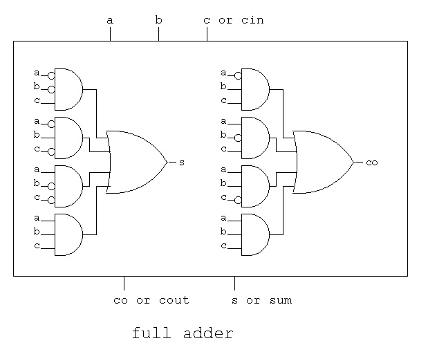
The hardware adder has a carry-in input that implements
the "add one" by making this input a "1".
Basic one bit adder, called a full adder.
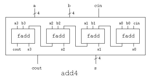
 Combining four full adders to make a 4-bit adder.
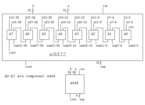
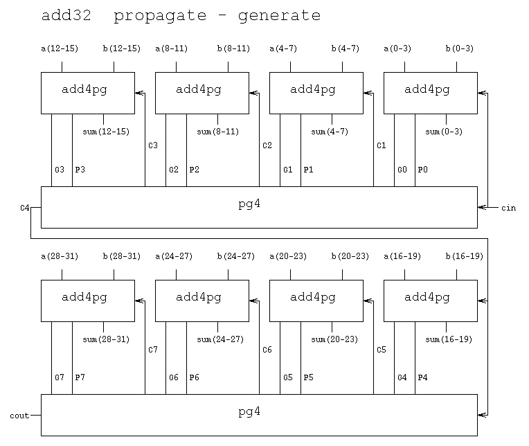
 Combining eight 4-bit adders to make a 32-bit adder.
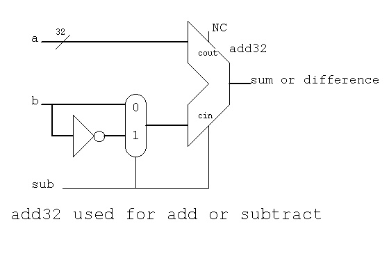
 A quick look at VHDL that implements the above diagrams,
with some optimization, is an add32
Using a multiplexor with 32-bit adder for subtraction.
"sub" is '1' for subtract, '0' for add.
(NC is no connection, use open in VHDL)
A quick look at VHDL that implements the above diagrams,
with some optimization, is an add32
Using a multiplexor with 32-bit adder for subtraction.
"sub" is '1' for subtract, '0' for add.
(NC is no connection, use open in VHDL)
 There are many types of adders. "Bit slice" will be covered in the
next lecture on the ALU. First, related to Homework 4 is the
"propagate generate" adder, then the "Square root N" adder for
Computer Engineering majors.
The "Propagate Generate" PG adder has a propagation time
proportional to log_2 N for N bits.
There are many types of adders. "Bit slice" will be covered in the
next lecture on the ALU. First, related to Homework 4 is the
"propagate generate" adder, then the "Square root N" adder for
Computer Engineering majors.
The "Propagate Generate" PG adder has a propagation time
proportional to log_2 N for N bits.
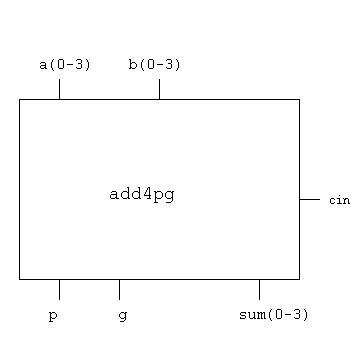
 The "add4pg" unit has four full adders and extra circuits,
defined by equations rather than logic gates:
-- add4pg.vhdl entity and architecture
-- for 4 bits of a propagate-generate, pg, adder
library IEEE;
use IEEE.std_logic_1164.all;
entity add4pg is
port(a : in std_logic_vector(3 downto 0);
b : in std_logic_vector(3 downto 0);
cin : in std_logic;
sum : out std_logic_vector(3 downto 0);
p : out std_logic;
g : out std_logic );
end entity add4pg ;
architecture circuits of add4pg is
signal c : std_logic_vector(2 downto 0);
begin -- circuits of add4pg
sum(0) <= a(0) xor b(0) xor cin after 2 ps;
c(0) <= (a(0) and b(0)) or (a(0) and cin) or (b(0) and cin) after 2 ps;
sum(1) <= a(1) xor b(1) xor c(0) after 2 ps;
c(1) <= (a(1) and b(1)) or
(a(1) and a(0) and b(0)) or
(a(1) and a(0) and cin) or
(a(1) and b(0) and cin) or
(b(1) and a(0) and b(0)) or
(b(1) and a(0) and cin) or
(b(1) and b(0) and cin) after 2 ps;
sum(2) <= a(2) xor b(2) xor c(1) after 2 ps;
c(2) <= (a(2) and b(2)) or (a(2) and c(1)) or (b(2) and c(1)) after 2 ps;
sum(3) <= a(3) xor b(3) xor c(2) after 2 ps;
p <= (a(0) or b(0)) and (a(1) or b(1)) and
(a(2) or b(2)) and (a(3) or b(3)) after 2 ps;
g <= (a(3) and b(3)) or ((a(3) or b(3)) and
((a(2) and b(2)) or ((a(2) or b(2)) and
((a(1) and b(1)) or ((a(1) or b(1)) and
((a(0) and b(0)))))))) after 2 ps;
end architecture circuits; -- of add4pg
The "PG4" box is defined by equations and thus no schematic:
-- pg4.vhdl entity and architecture Carry-Lookahead unit
-- pg4 is driven by four add4pg entities
library IEEE;
use IEEE.std_logic_1164.all;
entity pg4 is
port(p0 : in std_logic;
p1 : in std_logic;
p2 : in std_logic;
p3 : in std_logic;
g0 : in std_logic;
g1 : in std_logic;
g2 : in std_logic;
g3 : in std_logic;
cin : in std_logic;
c1 : out std_logic;
c2 : out std_logic;
c3 : out std_logic;
c4 : out std_logic);
end entity pg4 ;
architecture circuits of pg4 is
begin -- circuits of pg4
c1 <= g0 or (p0 and cin) after 2 ps;
c2 <= g1 or (p1 and g0) or (p1 and p0 and cin) after 2 ps;
c3 <= g2 or (p2 and g1) or (p2 and p1 and g0) or
(p2 and p1 and p0 and cin) after 2 ps;
c4 <= g3 or
(p3 and g2) or
(p3 and p2 and g1) or
(p3 and p2 and p1 and g0) or
(p3 and p2 and p1 and p0 and cin) after 2 ps;
end architecture circuits; -- of pg4
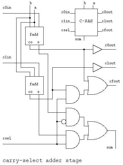
The "Carry Select" CS, adder gets increased speed from computing
the possible output with carry in to that stage being both
'0' and '1'. The "Carry Select" adder has a propagation time
proportional to sqrt(N) for N bits.
The "add4pg" unit has four full adders and extra circuits,
defined by equations rather than logic gates:
-- add4pg.vhdl entity and architecture
-- for 4 bits of a propagate-generate, pg, adder
library IEEE;
use IEEE.std_logic_1164.all;
entity add4pg is
port(a : in std_logic_vector(3 downto 0);
b : in std_logic_vector(3 downto 0);
cin : in std_logic;
sum : out std_logic_vector(3 downto 0);
p : out std_logic;
g : out std_logic );
end entity add4pg ;
architecture circuits of add4pg is
signal c : std_logic_vector(2 downto 0);
begin -- circuits of add4pg
sum(0) <= a(0) xor b(0) xor cin after 2 ps;
c(0) <= (a(0) and b(0)) or (a(0) and cin) or (b(0) and cin) after 2 ps;
sum(1) <= a(1) xor b(1) xor c(0) after 2 ps;
c(1) <= (a(1) and b(1)) or
(a(1) and a(0) and b(0)) or
(a(1) and a(0) and cin) or
(a(1) and b(0) and cin) or
(b(1) and a(0) and b(0)) or
(b(1) and a(0) and cin) or
(b(1) and b(0) and cin) after 2 ps;
sum(2) <= a(2) xor b(2) xor c(1) after 2 ps;
c(2) <= (a(2) and b(2)) or (a(2) and c(1)) or (b(2) and c(1)) after 2 ps;
sum(3) <= a(3) xor b(3) xor c(2) after 2 ps;
p <= (a(0) or b(0)) and (a(1) or b(1)) and
(a(2) or b(2)) and (a(3) or b(3)) after 2 ps;
g <= (a(3) and b(3)) or ((a(3) or b(3)) and
((a(2) and b(2)) or ((a(2) or b(2)) and
((a(1) and b(1)) or ((a(1) or b(1)) and
((a(0) and b(0)))))))) after 2 ps;
end architecture circuits; -- of add4pg
The "PG4" box is defined by equations and thus no schematic:
-- pg4.vhdl entity and architecture Carry-Lookahead unit
-- pg4 is driven by four add4pg entities
library IEEE;
use IEEE.std_logic_1164.all;
entity pg4 is
port(p0 : in std_logic;
p1 : in std_logic;
p2 : in std_logic;
p3 : in std_logic;
g0 : in std_logic;
g1 : in std_logic;
g2 : in std_logic;
g3 : in std_logic;
cin : in std_logic;
c1 : out std_logic;
c2 : out std_logic;
c3 : out std_logic;
c4 : out std_logic);
end entity pg4 ;
architecture circuits of pg4 is
begin -- circuits of pg4
c1 <= g0 or (p0 and cin) after 2 ps;
c2 <= g1 or (p1 and g0) or (p1 and p0 and cin) after 2 ps;
c3 <= g2 or (p2 and g1) or (p2 and p1 and g0) or
(p2 and p1 and p0 and cin) after 2 ps;
c4 <= g3 or
(p3 and g2) or
(p3 and p2 and g1) or
(p3 and p2 and p1 and g0) or
(p3 and p2 and p1 and p0 and cin) after 2 ps;
end architecture circuits; -- of pg4
The "Carry Select" CS, adder gets increased speed from computing
the possible output with carry in to that stage being both
'0' and '1'. The "Carry Select" adder has a propagation time
proportional to sqrt(N) for N bits.
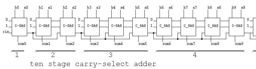 The above diagram has only 10 bits drawn.
You need 32 bits. Thus you need additional group of 5,
group of 6, group of 7, and a final group of 4.
1+2+3+4+5+6+7+4=32
The above diagram has only 10 bits drawn.
You need 32 bits. Thus you need additional group of 5,
group of 6, group of 7, and a final group of 4.
1+2+3+4+5+6+7+4=32
Monday, June 24, 2013
Arithmetic
Subscribe to:
Post Comments (Atom)
No comments:
Post a Comment