Mass-Storage Structure
Overview of Mass-Storage Structure
10.1.1 Magnetic Disks
- Traditional magnetic disks have the following basic structure:
- One or more platters in the form of disks covered with magnetic media. Hard disk platters are made of rigid metal, while "floppy" disks are made of more flexible plastic.
- Each platter has two working surfaces. Older hard disk drives would sometimes not use the very top or bottom surface of a stack of platters, as these surfaces were more susceptible to potential damage.
- Each working surface is divided into a number of concentric rings called tracks. The collection of all tracks that are the same distance from the edge of the platter, ( i.e. all tracks immediately above one another in the following diagram ) is called a cylinder.
- Each track is further divided into sectors, traditionally containing 512 bytes of data each, although some modern disks occasionally use larger sector sizes. ( Sectors also include a header and a trailer, including checksum information among other things. Larger sector sizes reduce the fraction of the disk consumed by headers and trailers, but increase internal fragmentation and the amount of disk that must be marked bad in the case of errors. )
- The data on a hard drive is read by read-write heads. The standard configuration ( shown below ) uses one head per surface, each on a separate arm, and controlled by a common arm assembly which moves all heads simultaneously from one cylinder to another. ( Other configurations, including independent read-write heads, may speed up disk access, but involve serious technical difficulties. )
- The storage capacity of a traditional disk drive is equal to the number of heads ( i.e. the number of working surfaces ), times the number of tracks per surface, times the number of sectors per track, times the number of bytes per sector. A particular physical block of data is specified by providing the head-sector-cylinder number at which it is located.
 Figure 10.1
- In operation the disk rotates at high speed, such as 7200 rpm ( 120 revolutions per second. ) The rate at which data can be transferred from the disk to the computer is composed of several steps:
- The positioning time, a.k.a. the seek time or random access time is the time required to move the heads from one cylinder to another, and for the heads to settle down after the move. This is typically the slowest step in the process and the predominant bottleneck to overall transfer rates.
- The rotational latency is the amount of time required for the desired sector to rotate around and come under the read-write head.This can range anywhere from zero to one full revolution, and on the average will equal one-half revolution. This is another physical step and is usually the second slowest step behind seek time. ( For a disk rotating at 7200 rpm, the average rotational latency would be 1/2 revolution / 120 revolutions per second, or just over 4 milliseconds, a long time by computer standards.
- The transfer rate, which is the time required to move the data electronically from the disk to the computer. ( Some authors may also use the term transfer rate to refer to the overall transfer rate, including seek time and rotational latency as well as the electronic data transfer rate. )
- Disk heads "fly" over the surface on a very thin cushion of air. If they should accidentally contact the disk, then a head crash occurs, which may or may not permanently damage the disk or even destroy it completely. For this reason it is normal to park the disk heads when turning a computer off, which means to move the heads off the disk or to an area of the disk where there is no data stored.
- Floppy disks are normally removable. Hard drives can also be removable, and some are even hot-swappable, meaning they can be removed while the computer is running, and a new hard drive inserted in their place.
- Disk drives are connected to the computer via a cable known as the I/O Bus. Some of the common interface formats include Enhanced Integrated Drive Electronics, EIDE; Advanced Technology Attachment, ATA; Serial ATA, SATA, Universal Serial Bus, USB; Fiber Channel, FC, and Small Computer Systems Interface, SCSI.
- The host controller is at the computer end of the I/O bus, and the disk controller is built into the disk itself. The CPU issues commands to the host controller via I/O ports. Data is transferred between the magnetic surface and onboard cache by the disk controller, and then the data is transferred from that cache to the host controller and the motherboard memory at electronic speeds.
10.1.2 Solid-State Disks - New
- As technologies improve and economics change, old technologies are often used in different ways. One example of this is the increasing used of solid state disks, or SSDs.
- SSDs use memory technology as a small fast hard disk. Specific implementations may use either flash memory or DRAM chips protected by a battery to sustain the information through power cycles.
- Because SSDs have no moving parts they are much faster than traditional hard drives, and certain problems such as the scheduling of disk accesses simply do not apply.
- However SSDs also have their weaknesses: They are more expensive than hard drives, generally not as large, and may have shorter life spans.
- SSDs are especially useful as a high-speed cache of hard-disk information that must be accessed quickly. One example is to store filesystem meta-data, e.g. directory and inode information, that must be accessed quickly and often. Another variation is a boot disk containing the OS and some application executables, but no vital user data. SSDs are also used in laptops to make them smaller, faster, and lighter.
- Because SSDs are so much faster than traditional hard disks, the throughput of the bus can become a limiting factor, causing some SSDs to be connected directly to the system PCI bus for example.
10.1.3 Magnetic Tapes - was 12.1.2
- Magnetic tapes were once used for common secondary storage before the days of hard disk drives, but today are used primarily for backups.
- Accessing a particular spot on a magnetic tape can be slow, but once reading or writing commences, access speeds are comparable to disk drives.
- Capacities of tape drives can range from 20 to 200 GB, and compression can double that capacity.
10.2 Disk Structure
- The traditional head-sector-cylinder, HSC numbers are mapped to linear block addresses by numbering the first sector on the first head on the outermost track as sector 0. Numbering proceeds with the rest of the sectors on that same track, and then the rest of the tracks on the same cylinder before proceeding through the rest of the cylinders to the center of the disk. In modern practice these linear block addresses are used in place of the HSC numbers for a variety of reasons:
- The linear length of tracks near the outer edge of the disk is much longer than for those tracks located near the center, and therefore it is possible to squeeze many more sectors onto outer tracks than onto inner ones.
- All disks have some bad sectors, and therefore disks maintain a few spare sectors that can be used in place of the bad ones. The mapping of spare sectors to bad sectors in managed internally to the disk controller.
- Modern hard drives can have thousands of cylinders, and hundreds of sectors per track on their outermost tracks. These numbers exceed the range of HSC numbers for many ( older ) operating systems, and therefore disks can be configured for any convenient combination of HSC values that falls within the total number of sectors physically on the drive.
- There is a limit to how closely packed individual bits can be placed on a physical media, but that limit is growing increasingly more packed as technological advances are made.
- Modern disks pack many more sectors into outer cylinders than inner ones, using one of two approaches:
- With Constant Linear Velocity, CLV, the density of bits is uniform from cylinder to cylinder. Because there are more sectors in outer cylinders, the disk spins slower when reading those cylinders, causing the rate of bits passing under the read-write head to remain constant. This is the approach used by modern CDs and DVDs.
- With Constant Angular Velocity, CAV, the disk rotates at a constant angular speed, with the bit density decreasing on outer cylinders. ( These disks would have a constant number of sectors per track on all cylinders. )
10.3 Disk Attachment
Disk drives can be attached either directly to a particular host ( a local disk ) or to a network.
10.3.1 Host-Attached Storage
- Local disks are accessed through I/O Ports as described earlier.
- The most common interfaces are IDE or ATA, each of which allow up to two drives per host controller.
- SATA is similar with simpler cabling.
- High end workstations or other systems in need of larger number of disks typically use SCSI disks:
- The SCSI standard supports up to 16 targets on each SCSI bus, one of which is generally the host adapter and the other 15 of which can be disk or tape drives.
- A SCSI target is usually a single drive, but the standard also supports up to 8 units within each target. These would generally be used for accessing individual disks within a RAID array. ( See below. )
- The SCSI standard also supports multiple host adapters in a single computer, i.e. multiple SCSI busses.
- Modern advancements in SCSI include "fast" and "wide" versions, as well as SCSI-2.
- SCSI cables may be either 50 or 68 conductors. SCSI devices may be external as well as internal.
- See wikipedia for more information on the SCSI interface.
- FC is a high-speed serial architecture that can operate over optical fiber or four-conductor copper wires, and has two variants:
- A large switched fabric having a 24-bit address space. This variant allows for multiple devices and multiple hosts to interconnect, forming the basis for the storage-area networks, SANs, to be discussed in a future section.
- The arbitrated loop, FC-AL, that can address up to 126 devices ( drives and controllers. )
10.3.2 Network-Attached Storage
- Network attached storage connects storage devices to computers using a remote procedure call, RPC, interface, typically with something like NFS filesystem mounts. This is convenient for allowing several computers in a group common access and naming conventions for shared storage.
- NAS can be implemented using SCSI cabling, or ISCSI uses Internet protocols and standard network connections, allowing long-distance remote access to shared files.
- NAS allows computers to easily share data storage, but tends to be less efficient than standard host-attached storage.
 Figure 10.2
10.3.3 Storage-Area Network
- A Storage-Area Network, SAN, connects computers and storage devices in a network, using storage protocols instead of network protocols.
- One advantage of this is that storage access does not tie up regular networking bandwidth.
- SAN is very flexible and dynamic, allowing hosts and devices to attach and detach on the fly.
- SAN is also controllable, allowing restricted access to certain hosts and devices.
 Figure 10.3
10.4 Disk Scheduling
- As mentioned earlier, disk transfer speeds are limited primarily by seek times and rotational latency. When multiple requests are to be processed there is also some inherent delay in waiting for other requests to be processed.
- Bandwidth is measured by the amount of data transferred divided by the total amount of time from the first request being made to the last transfer being completed, ( for a series of disk requests. )
- Both bandwidth and access time can be improved by processing requests in a good order.
- Disk requests include the disk address, memory address, number of sectors to transfer, and whether the request is for reading or writing.
10.4.1 FCFS Scheduling
- First-Come First-Serve is simple and intrinsically fair, but not very efficient. Consider in the following sequence the wild swing from cylinder 122 to 14 and then back to 124:
 Figure 10.4
10.4.2 SSTF Scheduling
- Shortest Seek Time First scheduling is more efficient, but may lead to starvation if a constant stream of requests arrives for the same general area of the disk.
- SSTF reduces the total head movement to 236 cylinders, down from 640 required for the same set of requests under FCFS. Note, however that the distance could be reduced still further to 208 by starting with 37 and then 14 first before processing the rest of the requests.
 Figure 10.5
10.4.3 SCAN Scheduling
- The SCAN algorithm, a.k.a. the elevator algorithm moves back and forth from one end of the disk to the other, similarly to an elevator processing requests in a tall building.
 Figure 10.6
- Under the SCAN algorithm, If a request arrives just ahead of the moving head then it will be processed right away, but if it arrives just after the head has passed, then it will have to wait for the head to pass going the other way on the return trip. This leads to a fairly wide variation in access times which can be improved upon.
- Consider, for example, when the head reaches the high end of the disk: Requests with high cylinder numbers just missed the passing head, which means they are all fairly recent requests, whereas requests with low numbers may have been waiting for a much longer time. Making the return scan from high to low then ends up accessing recent requests first and making older requests wait that much longer.
10.4.4 C-SCAN Scheduling
- The Circular-SCAN algorithm improves upon SCAN by treating all requests in a circular queue fashion - Once the head reaches the end of the disk, it returns to the other end without processing any requests, and then starts again from the beginning of the disk:
 Figure 10.7
12.4.5 LOOK Scheduling
- LOOK scheduling improves upon SCAN by looking ahead at the queue of pending requests, and not moving the heads any farther towards the end of the disk than is necessary. The following diagram illustrates the circular form of LOOK:
 Figure 10.8
10.4.6 Selection of a Disk-Scheduling Algorithm
- With very low loads all algorithms are equal, since there will normally only be one request to process at a time.
- For slightly larger loads, SSTF offers better performance than FCFS, but may lead to starvation when loads become heavy enough.
- For busier systems, SCAN and LOOK algorithms eliminate starvation problems.
- The actual optimal algorithm may be something even more complex than those discussed here, but the incremental improvements are generally not worth the additional overhead.
- Some improvement to overall filesystem access times can be made by intelligent placement of directory and/or inode information. If those structures are placed in the middle of the disk instead of at the beginning of the disk, then the maximum distance from those structures to data blocks is reduced to only one-half of the disk size. If those structures can be further distributed and furthermore have their data blocks stored as close as possible to the corresponding directory structures, then that reduces still further the overall time to find the disk block numbers and then access the corresponding data blocks.
- On modern disks the rotational latency can be almost as significant as the seek time, however it is not within the OSes control to account for that, because modern disks do not reveal their internal sector mapping schemes, ( particularly when bad blocks have been remapped to spare sectors. )
- Some disk manufacturers provide for disk scheduling algorithms directly on their disk controllers, ( which do know the actual geometry of the disk as well as any remapping ), so that if a series of requests are sent from the computer to the controller then those requests can be processed in an optimal order.
- Unfortunately there are some considerations that the OS must take into account that are beyond the abilities of the on-board disk-scheduling algorithms, such as priorities of some requests over others, or the need to process certain requests in a particular order. For this reason OSes may elect to spoon-feed requests to the disk controller one at a time in certain situations.
10.5 Disk Management
105.1 Disk Formatting
- Before a disk can be used, it has to be low-level formatted, which means laying down all of the headers and trailers marking the beginning and ends of each sector. Included in the header and trailer are the linear sector numbers, and error-correcting codes, ECC, which allow damaged sectors to not only be detected, but in many cases for the damaged data to be recovered ( depending on the extent of the damage. ) Sector sizes are traditionally 512 bytes, but may be larger, particularly in larger drives.
- ECC calculation is performed with every disk read or write, and if damage is detected but the data is recoverable, then a soft error has occurred. Soft errors are generally handled by the on-board disk controller, and never seen by the OS. ( See below. )
- Once the disk is low-level formatted, the next step is to partition the drive into one or more separate partitions. This step must be completed even if the disk is to be used as a single large partition, so that the partition table can be written to the beginning of the disk.
- After partitioning, then the filesystems must be logically formatted, which involves laying down the master directory information ( FAT table or inode structure ), initializing free lists, and creating at least the root directory of the filesystem. ( Disk partitions which are to be used as raw devices are not logically formatted. This saves the overhead and disk space of the filesystem structure, but requires that the application program manage its own disk storage requirements. )
10.5.2 Boot Block
- Computer ROM contains a bootstrap program ( OS independent ) with just enough code to find the first sector on the first hard drive on the first controller, load that sector into memory, and transfer control over to it. ( The ROM bootstrap program may look in floppy and/or CD drives before accessing the hard drive, and is smart enough to recognize whether it has found valid boot code or not. )
- The first sector on the hard drive is known as the Master Boot Record, MBR, and contains a very small amount of code in addition to the partition table. The partition table documents how the disk is partitioned into logical disks, and indicates specifically which partition is the active or boot partition.
- The boot program then looks to the active partition to find an operating system, possibly loading up a slightly larger / more advanced boot program along the way.
- In a dual-boot ( or larger multi-boot ) system, the user may be given a choice of which operating system to boot, with a default action to be taken in the event of no response within some time frame.
- Once the kernel is found by the boot program, it is loaded into memory and then control is transferred over to the OS. The kernel will normally continue the boot process by initializing all important kernel data structures, launching important system services ( e.g. network daemons, sched, init, etc. ), and finally providing one or more login prompts. Boot options at this stage may include single-user a.k.a.maintenance or safe modes, in which very few system services are started - These modes are designed for system administrators to repair problems or otherwise maintain the system.
 Figure 10.9
10.5.3 Bad Blocks
- No disk can be manufactured to 100% perfection, and all physical objects wear out over time. For these reasons all disks are shipped with a few bad blocks, and additional blocks can be expected to go bad slowly over time. If a large number of blocks go bad then the entire disk will need to be replaced, but a few here and there can be handled through other means.
- In the old days, bad blocks had to be checked for manually. Formatting of the disk or running certain disk-analysis tools would identify bad blocks, and attempt to read the data off of them one last time through repeated tries. Then the bad blocks would be mapped out and taken out of future service. Sometimes the data could be recovered, and sometimes it was lost forever. ( Disk analysis tools could be either destructive or non-destructive. )
- Modern disk controllers make much better use of the error-correcting codes, so that bad blocks can be detected earlier and the data usually recovered. ( Recall that blocks are tested with every write as well as with every read, so often errors can be detected before the write operation is complete, and the data simply written to a different sector instead. )
- Note that re-mapping of sectors from their normal linear progression can throw off the disk scheduling optimization of the OS, especially if the replacement sector is physically far away from the sector it is replacing. For this reason most disks normally keep a few spare sectors on each cylinder, as well as at least one spare cylinder. Whenever possible a bad sector will be mapped to another sector on the same cylinder, or at least a cylinder as close as possible. Sector slipping may also be performed, in which all sectors between the bad sector and the replacement sector are moved down by one, so that the linear progression of sector numbers can be maintained.
- If the data on a bad block cannot be recovered, then a hard error has occurred., which requires replacing the file(s) from backups, or rebuilding them from scratch.
10.6 Swap-Space Management
- Modern systems typically swap out pages as needed, rather than swapping out entire processes. Hence the swapping system is part of the virtual memory management system.
- Managing swap space is obviously an important task for modern OSes.
10.6.1 Swap-Space Use
- The amount of swap space needed by an OS varies greatly according to how it is used. Some systems require an amount equal to physical RAM; some want a multiple of that; some want an amount equal to the amount by which virtual memory exceeds physical RAM, and some systems use little or none at all!
- Some systems support multiple swap spaces on separate disks in order to speed up the virtual memory system.
10.6.2 Swap-Space Location
Swap space can be physically located in one of two locations:
- As a large file which is part of the regular filesystem. This is easy to implement, but inefficient. Not only must the swap space be accessed through the directory system, the file is also subject to fragmentation issues. Caching the block location helps in finding the physical blocks, but that is not a complete fix.
- As a raw partition, possibly on a separate or little-used disk. This allows the OS more control over swap space management, which is usually faster and more efficient. Fragmentation of swap space is generally not a big issue, as the space is re-initialized every time the system is rebooted. The downside of keeping swap space on a raw partition is that it can only be grown by repartitioning the hard drive.
12.6.3 Swap-Space Management: An Example
- Historically OSes swapped out entire processes as needed. Modern systems swap out only individual pages, and only as needed. ( For example process code blocks and other blocks that have not been changed since they were originally loaded are normally just freed from the virtual memory system rather than copying them to swap space, because it is faster to go find them again in the filesystem and read them back in from there than to write them out to swap space and then read them back. )
- In the mapping system shown below for Linux systems, a map of swap space is kept in memory, where each entry corresponds to a 4K block in the swap space. Zeros indicate free slots and non-zeros refer to how many processes have a mapping to that particular block ( >1 for shared pages only. )
 Figure 10.10
10.7 RAID Structure
- The general idea behind RAID is to employ a group of hard drives together with some form of duplication, either to increase reliability or to speed up operations, ( or sometimes both. )
- RAID originally stood for Redundant Array of Inexpensive Disks, and was designed to use a bunch of cheap small disks in place of one or two larger more expensive ones. Today RAID systems employ large possibly expensive disks as their components, switching the definition to Independent disks.
10.7.1 Improvement of Reliability via Redundancy
- The more disks a system has, the greater the likelihood that one of them will go bad at any given time. Hence increasing disks on a system actually decreases the Mean Time To Failure, MTTF of the system.
- If, however, the same data was copied onto multiple disks, then the data would not be lost unless both ( or all ) copies of the data were damaged simultaneously, which is a MUCH lower probability than for a single disk going bad. More specifically, the second disk would have to go bad before the first disk was repaired, which brings the Mean Time To Repair into play. For example if two disks were involved, each with a MTTF of 100,000 hours and a MTTR of 10 hours, then the Mean Time to Data Loss would be 500 * 10^6 hours, or 57,000 years!
- This is the basic idea behind disk mirroring, in which a system contains identical data on two or more disks.
- Note that a power failure during a write operation could cause both disks to contain corrupt data, if both disks were writing simultaneously at the time of the power failure. One solution is to write to the two disks in series, so that they will not both become corrupted ( at least not in the same way ) by a power failure. And alternate solution involves non-volatile RAM as a write cache, which is not lost in the event of a power failure and which is protected by error-correcting codes.
10.7.2 Improvement in Performance via Parallelism
- There is also a performance benefit to mirroring, particularly with respect to reads. Since every block of data is duplicated on multiple disks, read operations can be satisfied from any available copy, and multiple disks can be reading different data blocks simultaneously in parallel. ( Writes could possibly be sped up as well through careful scheduling algorithms, but it would be complicated in practice. )
- Another way of improving disk access time is with striping, which basically means spreading data out across multiple disks that can be accessed simultaneously.
- With bit-level striping the bits of each byte are striped across multiple disks. For example if 8 disks were involved, then each 8-bit byte would be read in parallel by 8 heads on separate disks. A single disk read would access 8 * 512 bytes = 4K worth of data in the time normally required to read 512 bytes. Similarly if 4 disks were involved, then two bits of each byte could be stored on each disk, for 2K worth of disk access per read or write operation.
- Block-level striping spreads a filesystem across multiple disks on a block-by-block basis, so if block N were located on disk 0, then block N + 1 would be on disk 1, and so on. This is particularly useful when filesystems are accessed in clusters of physical blocks. Other striping possibilities exist, with block-level striping being the most common.
10.7.3 RAID Levels
- Mirroring provides reliability but is expensive; Striping improves performance, but does not improve reliability. Accordingly there are a number of different schemes that combine the principals of mirroring and striping in different ways, in order to balance reliability versus performance versus cost. These are described by different RAID levels, as follows: ( In the diagram that follows, "C" indicates a copy, and "P" indicates parity, i.e. checksum bits. )
- Raid Level 0 - This level includes striping only, with no mirroring.
- Raid Level 1 - This level includes mirroring only, no striping.
- Raid Level 2 - This level stores error-correcting codes on additional disks, allowing for any damaged data to be reconstructed by subtraction from the remaining undamaged data. Note that this scheme requires only three extra disks to protect 4 disks worth of data, as opposed to full mirroring. ( The number of disks required is a function of the error-correcting algorithms, and the means by which the particular bad bit(s) is(are) identified. )
- Raid Level 3 - This level is similar to level 2, except that it takes advantage of the fact that each disk is still doing its own error-detection, so that when an error occurs, there is no question about which disk in the array has the bad data. As a result a single parity bit is all that is needed to recover the lost data from an array of disks. Level 3 also includes striping, which improves performance. The downside with the parity approach is that every disk must take part in every disk access, and the parity bits must be constantly calculated and checked, reducing performance. Hardware-level parity calculations and NVRAM cache can help with both of those issues. In practice level 3 is greatly preferred over level 2.
- Raid Level 4 - This level is similar to level 3, employing block-level striping instead of bit-level striping. The benefits are that multiple blocks can be read independently, and changes to a block only require writing two blocks ( data and parity ) rather than involving all disks. Note that new disks can be added seamlessly to the system provided they are initialized to all zeros, as this does not affect the parity results.
- Raid Level 5 - This level is similar to level 4, except the parity blocks are distributed over all disks, thereby more evenly balancing the load on the system. For any given block on the disk(s), one of the disks will hold the parity information for that block and the other N-1 disks will hold the data. Note that the same disk cannot hold both data and parity for the same block, as both would be lost in the event of a disk crash.
- Raid Level 6 - This level extends raid level 5 by storing multiple bits of error-recovery codes, ( such as the Reed-Solomon codes ), for each bit position of data, rather than a single parity bit. In the example shown below 2 bits of ECC are stored for every 4 bits of data, allowing data recovery in the face of up to two simultaneous disk failures. Note that this still involves only 50% increase in storage needs, as opposed to 100% for simple mirroring which could only tolerate a single disk failure.
 Figure 10.11
- There are also two RAID levels which combine RAID levels 0 and 1 ( striping and mirroring ) in different combinations, designed to provide both performance and reliability at the expense of increased cost.
- RAID level 0 + 1 disks are first striped, and then the striped disks mirrored to another set. This level generally provides better performance than RAID level 5.
- RAID level 1 + 0 mirrors disks in pairs, and then stripes the mirrored pairs. The storage capacity, performance, etc. are all the same, but there is an advantage to this approach in the event of multiple disk failures, as illustrated below:.
- In diagram (a) below, the 8 disks have been divided into two sets of four, each of which is striped, and then one stripe set is used to mirror the other set.
- If a single disk fails, it wipes out the entire stripe set, but the system can keep on functioning using the remaining set.
- However if a second disk from the other stripe set now fails, then the entire system is lost, as a result of two disk failures.
- In diagram (b), the same 8 disks are divided into four sets of two, each of which is mirrored, and then the file system is striped across the four sets of mirrored disks.
- If a single disk fails, then that mirror set is reduced to a single disk, but the system rolls on, and the other three mirror sets continue mirroring.
- Now if a second disk fails, ( that is not the mirror of the already failed disk ), then another one of the mirror sets is reduced to a single disk, but the system can continue without data loss.
- In fact the second arrangement could handle as many as four simultaneously failed disks, as long as no two of them were from the same mirror pair.
- See the wikipedia article on nested raid levels for more information.
- Here's a better explanation: http://www.storagereview.com/guide2000/ref/hdd/perf/raid/levels/multXY.html
 Figure 10.12
10.7.4 Selecting a RAID Level
- Trade-offs in selecting the optimal RAID level for a particular application include cost, volume of data, need for reliability, need for performance, and rebuild time, the latter of which can affect the likelihood that a second disk will fail while the first failed disk is being rebuilt.
- Other decisions include how many disks are involved in a RAID set and how many disks to protect with a single parity bit. More disks in the set increases performance but increases cost. Protecting more disks per parity bit saves cost, but increases the likelihood that a second disk will fail before the first bad disk is repaired.
10.7.5 Extensions
- RAID concepts have been extended to tape drives ( e.g. striping tapes for faster backups or parity checking tapes for reliability ), and for broadcasting of data.
10.7.6 Problems with RAID
- RAID protects against physical errors, but not against any number of bugs or other errors that could write erroneous data.
- ZFS adds an extra level of protection by including data block checksums in all inodes along with the pointers to the data blocks. If data are mirrored and one copy has the correct checksum and the other does not, then the data with the bad checksum will be replaced with a copy of the data with the good checksum. This increases reliability greatly over RAID alone, at a cost of a performance hit that is acceptable because ZFS is so fast to begin with.
 Figure 10.13
- Another problem with traditional filesystems is that the sizes are fixed, and relatively difficult to change. Where RAID sets are involved it becomes even harder to adjust filesystem sizes, because a filesystem cannot span across multiple filesystems.
- ZFS solves these problems by pooling RAID sets, and by dynamically allocating space to filesystems as needed. Filesystem sizes can be limited by quotas, and space can also be reserved to guarantee that a filesystem will be able to grow later, but these parameters can be changed at any time by the filesystem's owner. Otherwise filesystems grow and shrink dynamically as needed.
 Figure 10.14
10.8 Stable-Storage Implementation ( Optional )
- The concept of stable storage ( first presented in chapter 6 ) involves a storage medium in which data is never lost, even in the face of equipment failure in the middle of a write operation.
- To implement this requires two ( or more ) copies of the data, with separate failure modes.
- An attempted disk write results in one of three possible outcomes:
- The data is successfully and completely written.
- The data is partially written, but not completely. The last block written may be garbled.
- No writing takes place at all.
- Whenever an equipment failure occurs during a write, the system must detect it, and return the system back to a consistent state. To do this requires two physical blocks for every logical block, and the following procedure:
- Write the data to the first physical block.
- After step 1 had completed, then write the data to the second physical block.
- Declare the operation complete only after both physical writes have completed successfully.
- During recovery the pair of blocks is examined.
- If both blocks are identical and there is no sign of damage, then no further action is necessary.
- If one block contains a detectable error but the other does not, then the damaged block is replaced with the good copy. ( This will either undo the operation or complete the operation, depending on which block is damaged and which is undamaged. )
- If neither block shows damage but the data in the blocks differ, then replace the data in the first block with the data in the second block. ( Undo the operation. )
- Because the sequence of operations described above is slow, stable storage usually includes NVRAM as a cache, and declares a write operation complete once it has been written to the NVRAM.
10.9 Summary
Was 12.9 Tertiary-Storage Structure - Optional, Omitted from Ninth Edition
- Primary storage refers to computer memory chips; Secondary storage refers to fixed-disk storage systems ( hard drives ); And Tertiary Storage refers to removable media, such as tape drives, CDs, DVDs, and to a lesser extend floppies, thumb drives, and other detachable devices.
- Tertiary storage is typically characterized by large capacity, low cost per MB, and slow access times, although there are exceptions in any of these categories.
- Tertiary storage is typically used for backups and for long-term archival storage of completed work. Another common use for tertiary storage is to swap large little-used files ( or groups of files ) off of the hard drive, and then swap them back in as needed in a fashion similar to secondary storage providing swap space for primary storage. ( Review The Paging Game, note 5 ).
12.9.1 Tertiary-Storage Devices
12.9.1.1 Removable Disks
- Removable magnetic disks ( e.g. floppies ) can be nearly as fast as hard drives, but are at greater risk for damage due to scratches. Variations of removable magnetic disks up to a GB or more in capacity have been developed. ( Hot-swappable hard drives? )
- A magneto-optical disk uses a magnetic disk covered in a clear plastic coating that protects the surface.
- The heads sit a considerable distance away from the magnetic surface, and as a result do not have enough magnetic strength to switch bits at normal room temperature.
- For writing, a laser is used to heat up a specific spot on the disk, to a temperature at which the weak magnetic field of the write head is able to flip the bits.
- For reading, a laser is shined at the disk, and the Kerr effect causes the polarization of the light to become rotated either clockwise or counter-clockwise depending on the orientation of the magnetic field.
- Optical disks do not use magnetism at all, but instead use special materials that can be altered ( by lasers ) to have relatively light or dark spots.
- For example the phase-change disk has a material that can be frozen into either a crystalline or an amorphous state, the latter of which is less transparent and reflects less light when a laser is bounced off a reflective surface under the material.
- Three powers of lasers are used with phase-change disks: (1) a low power laser is used to read the disk, without effecting the materials. (2) A medium power erases the disk, by melting and re-freezing the medium into a crystalline state, and (3) a high power writes to the disk by melting the medium and re-freezing it into the amorphous state.
- The most common examples of these disks are re-writable CD-RWs and DVD-RWs.
- An alternative to the disks described above are Write-Once Read-Many, WORM drives.
- The original version of WORM drives involved a thin layer of aluminum sandwiched between two protective layers of glass or plastic.
- Holes were burned in the aluminum to write bits.
- Because the holes could not be filled back in, there was no way to re-write to the disk. ( Although data could be erased by burning more holes. )
- WORM drives have important legal ramifications for data that must be stored for a very long time and must be provable in court as unaltered since it was originally written. ( Such as long-term storage of medical records. )
- Modern CD-R and DVD-R disks are examples of WORM drives that use organic polymer inks instead of an aluminum layer.
- Read-only disks are similar to WORM disks, except the bits are pressed onto the disk at the factory, rather than being burned on one by one. ( Seehttp://en.wikipedia.org/wiki/CD_manufacturing#Premastering for more information on CD manufacturing techniques. )
12.9.1.2 Tapes
- Tape drives typically cost more than disk drives, but the cost per MB of the tapes themselves is lower.
- Tapes are typically used today for backups, and for enormous volumes of data stored by certain scientific establishments. ( E.g. NASA's archive of space probe and satellite imagery, which is currently being downloaded from numerous sources faster than anyone can actually look at it. )
- Robotic tape changers move tapes from drives to archival tape libraries upon demand.
- ( Never underestimate the bandwidth of a station wagon full of tapes rolling down the highway! )
12.9.1.3 Future Technology
- Solid State Disks, SSDs, are becoming more and more popular.
- Holographic storage uses laser light to store images in a 3-D structure, and the entire data structure can be transferred in a single flash of laser light.
- Micro-Electronic Mechanical Systems, MEMS, employs the technology used for computer chip fabrication to create VERY tiny little machines. One example packs 10,000 read-write heads within a square centimeter of space, and as media are passed over it, all 10,000 heads can read data in parallel.
12.9.2 Operating-System Support
- The OS must provide support for tertiary storage as removable media, including the support to transfer data between different systems.
12.9.2.1 Application Interface
- File systems are typically not stored on tapes. ( It might be technically possible, but it is impractical. )
- Tapes are also not low-level formatted, and do not use fixed-length blocks. Rather data is written to tapes in variable length blocks as needed.
- Tapes are normally accessed as raw devices, requiring each application to determine how the data is to be stored and read back. Issues such as header contents and ASCII versus binary encoding ( and byte-ordering ) are generally application specific.
- Basic operations supported for tapes include locate( ), read( ), write( ), and read_position( ).
- ( Because of variable length writes ), writing to a tape erases all data that follows that point on the tape.
- Writing to a tape places the End of Tape ( EOT ) marker at the end of the data written.
- It is not possible to locate( ) to any spot past the EOT marker.
12.9.2.2 File Naming
- File naming conventions for removable media are not entirely uniquely specific, nor are they necessarily consistent between different systems. ( Two removable disks may contain files with the same name, and there is no clear way for the naming system to distinguish between them. )
- Fortunately music CDs have a common format, readable by all systems. Data CDs and DVDs have only a few format choices, making it easy for a system to support all known formats.
12.9.2.3 Hierarchical Storage Management
- Hierarchical storage involves extending file systems out onto tertiary storage, swapping files from hard drives to tapes in much the same manner as data blocks are swapped from memory to hard drives.
- A placeholder is generally left on the hard drive, storing information about the particular tape ( or other removable media ) on which the file has been swapped out to.
- A robotic system transfers data to and from tertiary storage as needed, generally automatically upon demand of the file(s) involved.
12.9.3 Performance Issues
12.9.3.1 Speed
- Sustained Bandwidth is the rate of data transfer during a large file transfer, once the proper tape is loaded and the file located.
- Effective Bandwidth is the effective overall rate of data transfer, including any overhead necessary to load the proper tape and find the file on the tape.
- Access Latency is all of the accumulated waiting time before a file can be actually read from tape. This includes the time it takes to find the file on the tape, the time to load the tape from the tape library, and the time spent waiting in the queue for the tape drive to become available.
- Clearly tertiary storage access is much slower than secondary access, although removable disks ( e.g. a CD jukebox ) have somewhat faster access than a tape library.
12.9.3.1 Reliability
- Fixed hard drives are generally more reliable than removable drives, because they are less susceptible to the environment.
- Optical disks are generally more reliable than magnetic media.
- A fixed hard drive crash can destroy all data, whereas an optical drive or tape drive failure will often not harm the data media, ( and certainly can't damage any media not in the drive at the time of the failure. )
- Tape drives are mechanical devices, and can wear out tapes over time, ( as the tape head is generally in much closer physical contact with the tape than disk heads are with platters. )
- Some drives may only be able to read tapes a few times whereas other drives may be able to re-use the same tapes millions of times.
- Backup tapes should be read after writing, to verify that the backup tape is readable. ( Unfortunately that may have been the LAST time that particular tape was readable, and the only way to be sure is to read it again, . . . )
- Long-term tape storage can cause degradation, as magnetic fields "drift" from one layer of tape to the adjacent layers. Periodic fast-forwarding and rewinding of tapes can help, by changing which section of tape lays against which other layers.
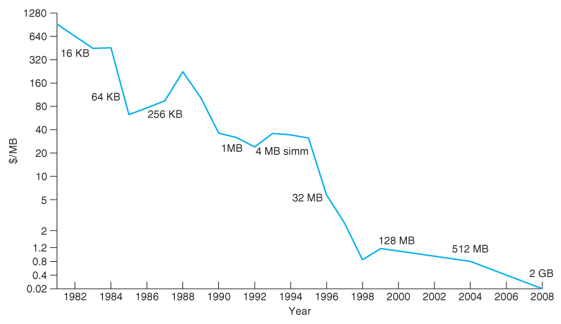
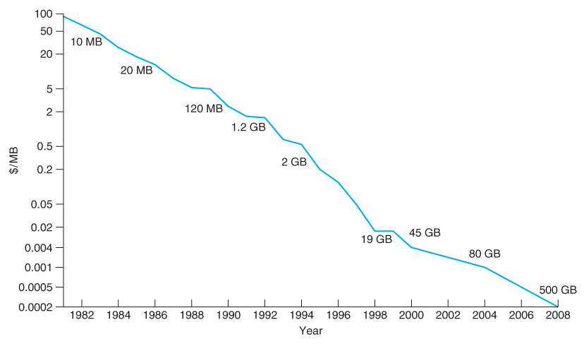
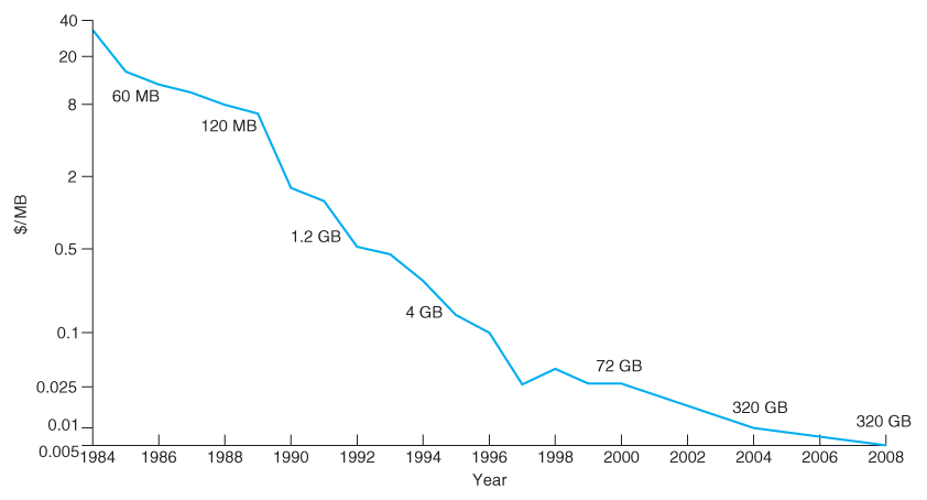
12.9.3.3 Cost
- The cost per megabyte for removable media is its strongest selling feature, particularly as the amount of storage involved ( i.e. the number of tapes, CDs, etc ) increases.
- However the cost per megabyte for hard drives has dropped more rapidly over the years than the cost of removable media, such that the currently most cost-effective backup solution for many systems is simply an additional ( external ) hard drive.
- ( One good use for old unwanted PCs is to put them on a network as a backup server and/or print server. The downside to this backup solution is that the backups are stored on-site with the original data, and a fire, flood, or burglary could wipe out both the original data and the backups. )
No comments:
Post a Comment